Due to the special requirements of some products, the mold release of some part is not consistent with the mold opening direction of the injection machine, which needs the side parting core pulling mechanism to eject the product smoothly.
The side parting core pulling mechanism comes with two types: slider(also known as slide) and lifter.
Slider/slide
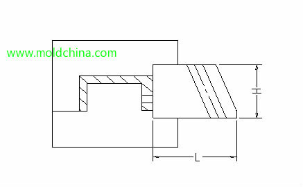
1. Slider travel calculation:
To ensure smooth product release, the travel distance of the slider has to be sufficient. Usually, the shortest travel distance that can guarantee smooth product release is 2 – 3mm:
AB = AC + (2 – 3)
2. All core sliders adopt the press plate + guide pin + spring structure as shown in the diagram (sometimes, when the slider is wider than 100 and yet it is not convenient to adopt the structure, T-plate structure may be considered). However, when the slider is vertically placed and restricted by pin position/mold size, press plate will not be necessary – an integrated mold base may be the option.
The press plate is a standard self-built part of the company, which shall be located with a locating pin.
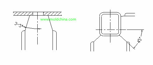
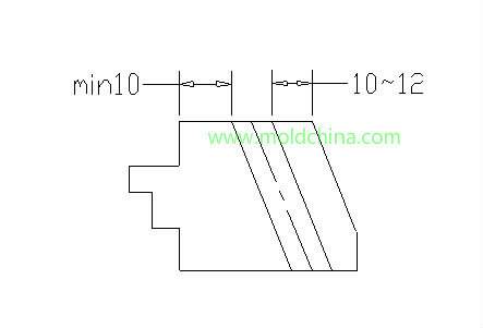
3. No matter whether the slider sides are sealed, both of its sides need a gradient design. Usually, the angle of a single side is 3 – 5 °; but when two sliders which travel in vertical direction join with one another, the angle will be 45°. During the design process, if there are sliders joining with one another on the four sides of a product, the ear of one of the sliders may stick out to guarantee accurate location.
4. The ratio of slider height to its length should be no greater than 1, or slider movement will be affected by overturning moment, leading to movement failure. General requirement: L≧1.5H.
5. Usually, the angle of a slider guide pin is 15° – 25°, with the biggest no larger than 25°. The angle of a guide pin is usually 2° smaller than that of the slider. In general, try not to use small guide pins, so as to ensure smooth slider movement.
6. The hole of a guide pin is 1/64" larger than a single side of it, about 0.4. When a guide pin goes through a slider, enough clearance should be kept on the mold plate.
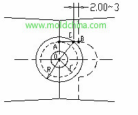
7. Identify the location of a guide pin in a slider: try to place the guide pin in the center of a slider. See the diagram for specific measurements:
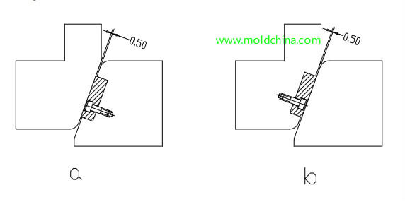
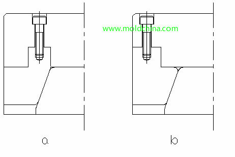
8. It is required that the wedge surface matched with the slider should be higher than 2/3 of slider height, and the screws used on wedges should as big as possible. The following diagrams show wedges of two different structures. Try to avoid the structure shown in diagram b.
9. Identification of slider spring length: Guarantee a sufficient space for spring, so as to avoid spring failure.
Assume slider travel is M and total spring length is L; assume the spring is compressed by 40%, and after the slider quits completely, the spring still bears 10% of the pressure, then:
(40%﹣10%)L=M
L=(10/3)M
Space for spring is 0.6L.
When L is too small, to prevent spring failure, spring length is often to be increased.
10. To ensure smooth slider movement, there cannot be obstacles to movement around it, such as pointed angles. Generally, chamfers of R3 – R5 should be designed around it.
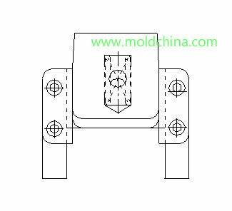
11. When a spring is needed to be mounted under a slider (see the diagram for dimensional requirements), to prevent screws from being seized by the spring, Table 4-1 should be referred to for selection of springs and screws.
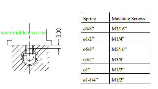
Spring Matching Screws
ø3/8” M3/16”
ø1/2” M1/4”
ø5/8” M5/16”
ø3/4” M3/8”
ø1” M1/2”
ø1-1/4” M1/2”
12. Large sliders should be cooled separately, and wear blocks should be fitted on the slider or the wedge. At this point, there should be a 0.5 clearance between the slider and the wedge.
See the diagrams.