Designing Your Plastic Part
When designing parts for injection molding, the manufacturing process is an important consideration. Injection molding is a process in which solid thermoplastic resin pellets are melted, injected into a mold, and then cooled back to a solid state in a new form. During Boss both the injection and cooling stages of the manufacturing process, there are several factors that may affect the quality of the final product and the repeatability of the custom mold manufacturing process. Although it is not always possible to follow all recommendations, outlined on the following pages are some of the most fundamental guidelines when designing parts for injection molding.
Radii
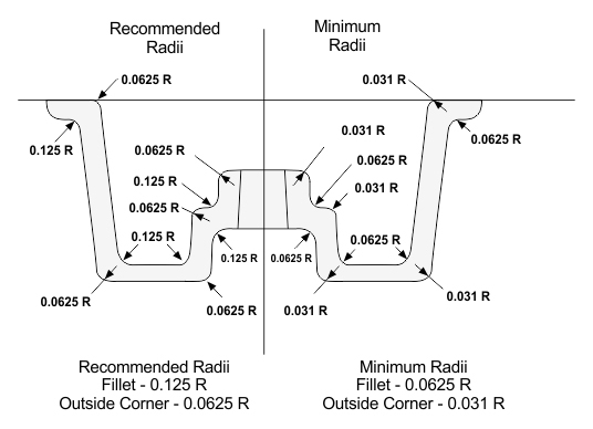
An inside radius should be at least 50 percent of the nominal wall thickness. An outside radius should be the nominal wall thickness plus the inside radius (150 percent of nominal wall). Sharp corners at the base of bosses and ribs can be stress concentrators. The edge where a boss meets the nominal wall should be radiused to reduce the sharp corner without increasing the wall thickness enough that it creates a sink problem. The radius at the base of a boss should be ¼ of the nominal wall with a minimum radius of 0.015”.
Design Recommendations:
Wall Thickness
- Maintain a wall thickness of less than 5mm because thick walls can lead to long cycle times and poor mechanical
properties.
- Avoid large variations in wall thicknesses in order to simplify flow pattern and minimize variations in shrinkage that can lead to warpage.
- Avoid abrupt changes in wall thickness, as this can create stress concentration areas that may reduce a part’s impact strength. Wall thickness changes should have transition zones that reduce the possibility of stress concentrations, sinks, voids, and warp.
- Avoid gating near an area with a large variation in wall thickness because hesitation and race tracking can create non-uniform flow and shrinkage.
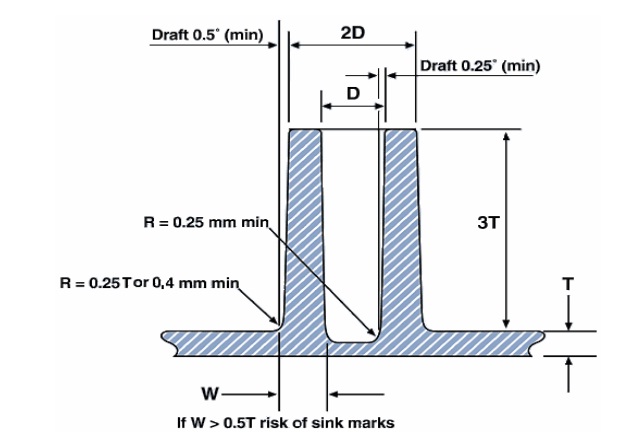
Ribs
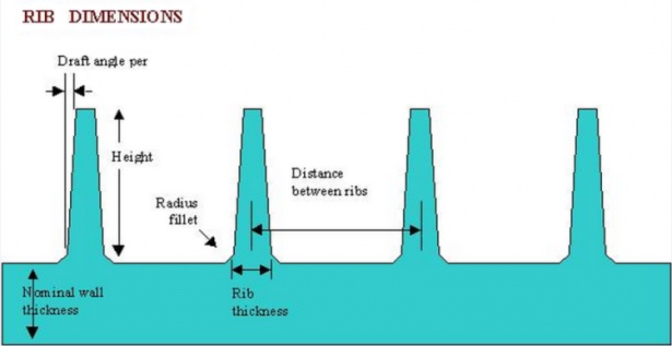
- Maximum rib thickness should be 0.5 to 0.75 of the nominal wall to avoid creating areas of sink.
- To avoid thin sections of steel in your mold, the distance between ribs should be at least two and a half times the nominal wall thickness.
- Ribs should have a draft angle of at least ½˚ per side in order to accommodate easier ejection from the mold.
- Maximum rib height should be no greater than three times the nominal wall thickness in order to avoid large variations in wall thickness.
- Balance ribs on both sides of the nominal wall to avoid non-uniform shrink that can lead to warpage.
Bosses
- Stand-alone bosses should be designed following the design guidelines for ribs
(see more information under the “Ribs” section).
- Use connecting ribs and/or supporting gussets if possible to stiffen structural parts. Connecting ribs should be 0.6 times the nominal wall thickness at their base to avoid sink.
- To maintain uniform wall thickness, bosses should be cored to the bottom of the boss.
Threads
Plastic threads used for joining parts can be machined or molded-in
- When designing molded-in threads, avoid feathered edges and include radiused roots in order to minimize stress concentrations and to keep the walls uniform.
- Sharp edges can be stress concentrators in plastic parts. Thread designs should consider this.
Draft Angle
- Design parts with a minimum of ½˚ per side draft in order to accommodate easier ejection from the mold.
Amorphous Versus Semi-Crystalline Materials:
In amorphous materials, molecules are randomly oriented and intertwined. Polymer molecules have no ordered structure. These materials have no identifiable “melting point” but progressively soften through a broad temperature range. Unfilled amorphous materials are typically isotropic, shrinking equally in the flow and transverse directions. Even fiber-filled amorphous materials typically have low shrink and good dimensional control.