Weld Lines
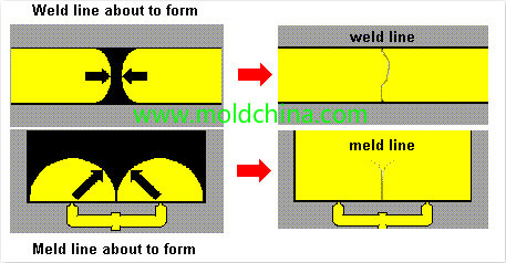
The flowing defects on product surface or the linear defects that are caused when melt fronts meet each other after splitting.
Weld lines refer to the lines that occur on a plastic product surface when the cold slug melts. In areas of mold cavity where the molten plastic meets inserts or holes, areas with inconsistent flow speed/flow interruptions, where multiple flows meet or when jetting happens during mold filling, linear weld marks tend to occur due to imperfect bonding. The existence of weld lines greatly compromises the mechanical strength of a product. The solution for overcoming weld lines is similar to that for reducing product sagging. Weld lines can be caused by many reasons, which covers the various aspects of mold, process, raw materials and product design, etc.
(1)Injection Machine
Poor plasticization and non-uniform melt temperature – appropriately extend the injection molding cycle, to ensure thorough plasticization, and change for a machine with a larger plasticization capacity when necessary.
(2)Mold
①Mold surface is too cold – appropriately raise mold temperature or purposefully increase the local temperature at melt joints, to restrict cooling speed.
②Runner is too thin, narrow or shallow, and cold slug well is too small – increase runner dimensions, improve runner efficiency and at the same time enlarge the area of the cold slug well.
③Increase or reduce the sectional area of the gate, and change gate location. Gate and runner are too small – increase gate size and runner diameter; gate is too far away from the welding area – need to change gate location or add dozzle(s); when deciding gate location, try to keep the melt from flowing around inserts or holes. When jetting occurs, the gate needs to be fixed, relocated or equipped with blocking buffers. And, try to avoid the application of multiple gates.
④Insufficient mold venting or no vent at all – set up, expand or clear the vents, including venting through insert and ejection pin clearances, setting up vents in welding areas or increasing vent dimensions.
⑤Too much detergent is used – try not to use release agent.
⑥Plastic part is too thin in the welding area – need to modify mold and thicken the area.
① Effective cavity pressure is too low – need to increase injection pressure and injection time.
②Increase injection speed. A high injection speed allows the molten plastic to reach the meeting point before cooling, while a low speed allows sufficient time to let cavity air out.
③Raise melt temperature or nozzle temperature; when the temperature is high, the plastic will feature a low viscosity and good fluidity, thus resulting in slighter weld lines; when the temperature is low, decomposition of gaseous substances can be reduced.
④Try not to use release agents, esp. those containing silicone, or the flows will not be able to bond perfectly.
⑤Reduce clamping force to ensure good ventilation.
⑥Appropriately increase back pressure and adjust screw speed, so as to ensure a uniform melt temperature; increase the screw speed to lower plastic viscosity; increase back pressure to improve plastic density.
(4)Raw Materials
①Ensure the raw materials are sufficiently dried. Dry the raw materials and try not to use liquid additives.
②Improve fluidity. For plastics that feature poor fluidity or high heat sensitivity, lubricants and stabilizers should be appropriately applied; choose materials with good fluidity and high thermal resistance when necessary.
(5)Product Design
①Small thickness – increase the thickness to avoid premature solidification.
②Inappropriate insert location – make appropriate adjustments.


